
The Mercedes-Benz 5G-TRONIC, also known as 722.6, is an electronically shifted 5-speed overdrive automatic transmission that was first introduced in 1996.
It has been used by a variety of vehicle manufacturers including Mercedes-Benz, Chrysler, Jaguar, Jeep, Dodge, and SsangYong. It only uses three planetary gear sets while the computer can command five forward speeds and two ratios for reverse.
The sophistication lies in the hydraulic and electronic control. Operation is achieved by the control of six solenoids situated on a conductor plate. This is attached to the valve body inside the transmission.
The hydraulic valve body controls and directs fluid pressure to the torque converter lock-up clutch, three holding clutches, and three driving clutches which allow for smooth shifting.
Handling Information
Input information comes from two speed sensors which are part of the conductor plate. Neither measure the input shaft (turbine) speed directly. Turbine speed is calculated from both sensors depending on the gear. Engine, speed, throttle, and accelerator position are provided by the engine control module. Vehicle speed is provided by the wheel speed sensors via the brake control module, which is done by CAN-BUS; this allows for an integrated system including inhibiting gear changes during hard cornering.
The transmission control module checks the sensors for plausibility and monitors solenoids for command and effect. By comparing engine speed and input shaft speed, it can monitor torque converter slip.
Through the monitoring of input shaft speed and wheel speed, it can monitor gear ratio, clutch slip, and account for tyre wear. By comparing actual values with the model programmed into the TCM, it can adapt for wear in the clutches by modulating shift pressure.
Electrical Sensing and Control
The conductor plate (febi no. 32342) carries the electrical sensing and control for the internals of the transmission. (Fig. 1)
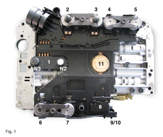
- N2 and N3 are two Hall Effect speed sensors – monitoring the speed of two separate rotating members and providing input shaft speed.
- Line pressure modulating solenoid – controlled by pulse width modulation (ground side).
- Shift pressure modulating solenoid – controlled by pulse width modulation (ground side)
- 1-2/4-5 12v gear shift solenoids – earth switched by the TCM.
- 3-4 12v gear shift solenoid – earth switched by the TCM.
- Torque converter lock-up clutch pressure control solenoid – controlled by pulse width modulation (ground side).
- 2-3 12v gear shift solenoid – earth switched by the TCM.
- Reed switch – closed by a magnet in a plunger and moved by the selector. It is in series with the temperature sensor with the purpose of indicating the Park and Neutral positions to impede the starting of the vehicle with a gear engaged.
- PTC temperature sensor thermistor – provides transmission oil temperature.
- Transmission fluid level sensor
- Float-ATF expansion plug
Replacing the Conductor Plate
When replacing a conductor plate, cleanliness is paramount. Any material entering the valve block may inhibit movement of the spool valves. Only use lint-free cloths. All bolts and fixings must be tightened to the manufacturers’ torque figures.
The following parts are required:
- 1 x 32342 Conductor plate
- 1 x 36332 Electrical plug
- 1 x 10072 Gasket
- 1 x 09463 Oil strainer
- 5 x 29449 1ltr ATF
- 1 x 38023 Dipstick
- 1 x 44204 Locking pin
Disassembly
Drain the Automatic Transmission Fluid (ATF); this is best done when the transmission is warm. Undo the drain plug and drain the ATF into a clean receptacle. This allows you to measure the quantity and check the fluid’s condition and for debris.
Allow the transmission to cool to an ambient temperature before proceeding with the dismantling process.
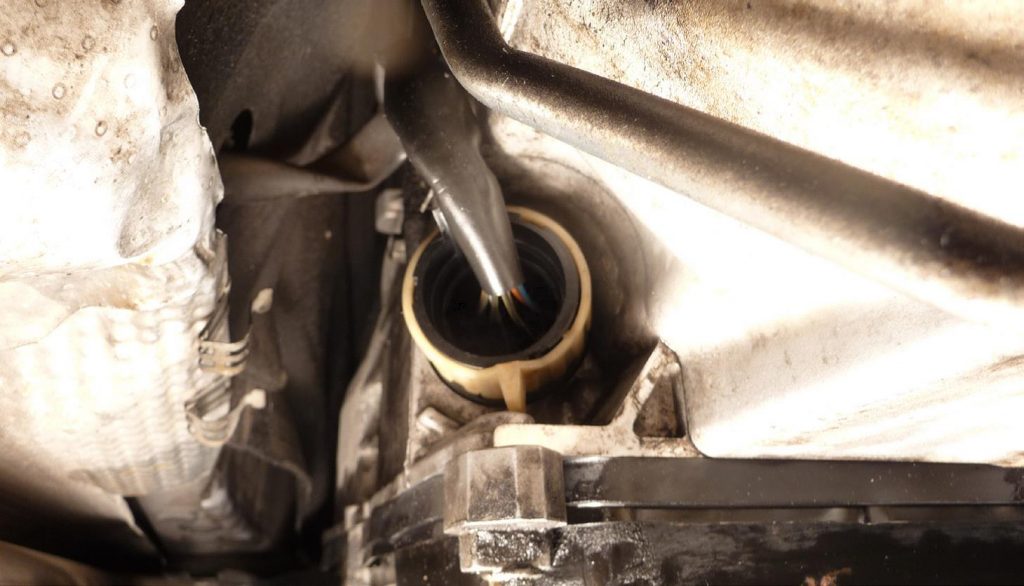
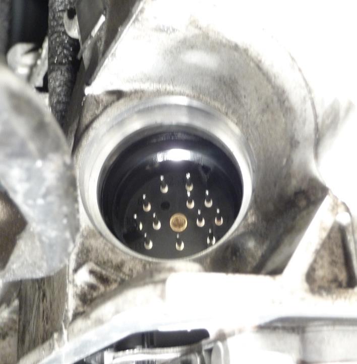
Remove the cover on the harness plug by inserting a small flat bladed screwdriver into the hole, carefully prying it out. Turn the lug on the tan collar counter-clockwise. It will click and jack-out the harness plug. (Fig. 2)
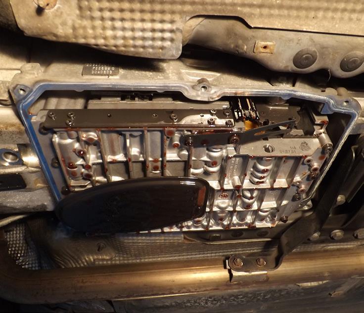
In the center of the plug is a 7mm bolt. Undo the bolt and pry out the guide sleeve. Refit the sump drain plug. Identify and remove the 10 Torx screws holding the valve body to the transmission. Remove the valve body paying close attention to the inhibitor plunger. (Fig. 3)
Inspect the drained transmission fluid. Darkened ATF and the smell of burning indicate heavy clutch wear/slip. If it has turned a pink color, or there is frothing, this could indicate cross contamination with the coolant. If any of these are noticed, further investigation and repair is required. There is likely to be a fine, dark gray film in the sump pan. This is perfectly normal. Inspect the sump magnet for metal pieces indicating more serious damage.
Reassembly
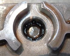
Work on a clean, prepared surface. With the valve body removed, remove the plastic solenoid covers from the valve body conductor plate and the 3 bolts holding the leaf springs. The solenoids can now be carefully removed. Remove the conductor plate from the valve body. The shift solenoids do not have O-rings. The pressure modulating solenoids have two. Inspect the O-rings and the ports where they fit. Inspect the port filters for debris. (Fig. 4)
Position the new conductor plate onto the valve body. There are two locating tabs that will snap into position. Lubricate the O-rings and push the solenoids into their ports while aligning the contacts. Refit the leaf springs and bolts and tighten. Refit the plastic solenoid covers.
Once back on the vehicle, wipe the surface of the mating face of the valve body with a lint free cloth. Refit the valve body locating the selector plunger on the selector sector; tighten the valve body retaining bolts. Lubricate the new filter O-ring and fit the new oil strainer. Make sure the barbs on the filter fit into the slot in the valve body. Lubricate and fit the new sump pan gasket and fit the sump pan to the transmission.
Consider All Connections
The conductor plate is connected to the outside of the transmission by a guide bush. This is sealed inside the conductor plate and the transmission casing by O-rings. A failure of these rings allows oil to enter the harness plug. Metal contaminants suspended in the ATF can cause short circuits. (Fig. 5)
Lubricate the guide bush O-rings and align the holes in the guide bush with the pins in the conductor plate. Push into place. Refit the harness plug turning the tan collar clockwise until resistance is felt. Turn it a further 30° until it clicks into its locked position. Measure the drained ATF to get an idea of how much was removed. Roughly five liters will be required.
Remove the red locking pin on the transmission filler tube and remove the plug. Replenish the oil through the dipstick/filler tube using a clean funnel or filler pipe with just less than the quantity you have removed.
Final Steps
Start the engine and let it idle for 2 minutes. Move the selector lever through the different positions resting for 10 seconds in each position. This will fill the clutches and expunge any air.
Very few 722.6 applications are fitted with an ATF fluid level dipstick. A dipstick will be necessary to measure the oil level if required (febi no. 38023).
The dipstick is approximately one meter long and is pushed into the transmission dipstick tube until it touches the bottom of the sump pan. A portion of the dipstick will be sticking out of the filler tube.
The transmission fluid has a very high rate of volumetric thermal expansion so there are two marks on the dipstick – a lower mark for measuring at 25 °C and a higher mark for measuring at 80 °C. With the engine warm, use a diagnostic tool to check the transmission temperature. The transmission must be in ‘D’ or ‘R’ to close the reed switch in the transmission fluid temperature sensor. In other positions, the value defaults to the coolant temperature. (Fig.6)

Take a measurement with the engine at idle and the fluid temperature resting at 80 °C.
Then, add fluid until it reaches the upper level. Replace the filler plug and perform a road test to check for proper operation.


